Line Following Robot
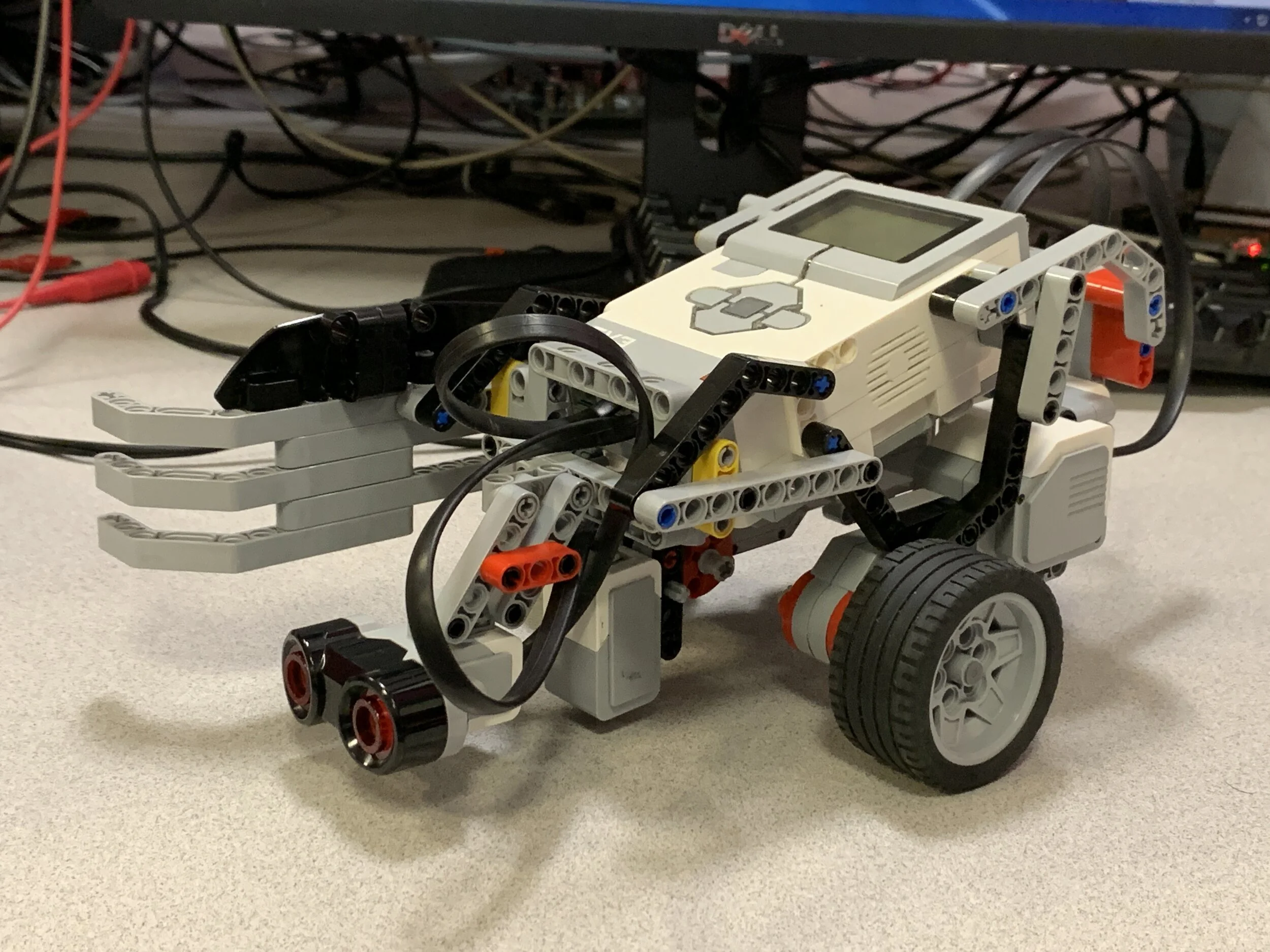
Codename: “SpiderBot”
Date: January 28, 2020
Project Type: University Assignment
Project Role: Mechanical Designer and RobotC Programmer
Project Partner: Ethan Holmes
Class: MSE110
Purpose: Design a functional robot using LEGO Mindstorms and RobotC which can follow a path defined using tape as quick and accurately as possible.
Additional Criteria: Depending on the colour of the tape the robot is following, either push obstacles out of the way or turn around and return along the tape line.
Method: Build a small robot with two motorized wheels to manoeuvre, one colour sensor to follow the tape line and assess tape colour, and one ultrasonic sensor to detect upcoming obstacles. Use PID (Proportional, Integral, Derivative) programming principles to optimize robot movements for speed.
Mechanical Design:
To minimize the robot footprint, the LEGO Mindstorms Brick (Control Unit) formed the basic structure of the robot with structural members attached to add functionality such as motorized wheels and sensors. The two wheel motors were placed as close to the midline as possible to maximize rotational travel for each wheel rotation for speed. The ultrasonic sensor had to be placed at the very front of the robot and angled so that robot components and surroundings such as the ground couldn't interfere with obstacle detection.
As navigation relied on reacting to colour sensor data, the colour sensor had to be placed forward of the robot's pivot point. The farther the colour sensor was from the central pivot axis, the finer the rotational control- adversely, if the sensor were too far forward, the robot body could deviate too far from the path during tight turns. To balance speed and path accuracy, the sensor was placed close to the pivot point and instead relied on PID programming to optimize the speed.
The final mechanical addition was an arm to push aside any obstacles which had to be moved away from the given course. A curved arm with two attachment sites ensured rigidity and kept clear of the conical range of the ultrasonic sensor. The colour sensor outputs integer values between 0-100 as reflection values or integer values between 0-7 as reflected light colour values, depending on its defined mode of operation.
Testing showed a distance of about 1-2 cm between the colour sensor and surface yielded the best results. Placing the sensor below the robot body also decreased external light changes which could affect the reflection values erroneously. A parallel link arm structure for the ultrasonic sensor simplified subsequent position testing and adjustment without the need to replace pieces each time.
Software Design:
First, the essential functions are listed: Detect line, move forwards, turn to stay on the line, detect obstacles, determine line colour, respond to obstacle, return to line following
Then, an approximate pseudocode:
While program is active
Locate line
Move forwards
Detect line reflection values
The greater the deviation from the threshold, the higher the correction factor (CF)
If reflection is above threshold
Increase speed (x CF) of one wheel to return to line
Else-if reflection is below threshold
Increase speed (x CF) of the other wheel to stay on the border of the line
If obstacle is detected
Stop and beep for two seconds
Place colour sensor above line
Change colour sensor from reflection to colour detection mode
Detect line colour
If line is blue
Push obstacle at least 10 cm away from line
Return to the line
Else-if line is green
Turn 180 degrees
End
The final test of the line following robot
Results:
The robot completed the course with appropriate responses to obstacles while maintaining desired proximity to the tape line. The PID implementation was effective in optimizing path corners, however did not optimize speeds during the straight segments. Additional testing for bonus points showed the robot was able to follow a 330 degree corner, but failed to follow the extreme 30 degree angle. During the 30 degree corner test, the wheels turned to realign with the right edge of the tape, as the wheels turned the colour sensor went beyond the left edge of the tape path and started adjusting its trajectory to locate the right edge- turning around and missing the turn altogether. The assessing teaching assistant graded the performance of this robot as an "A+".
An attempt for bonus marks with a tight corner
Conclusion:
The robot was reliable in following expected path metrics and reacting to obstacles as required for a given path colour. The overall performance could have been optimized by adding PID adjustment for the straight segments in addition to turns. To implement a straight-path optimization, the algorithm could compare subsequent results for variability between readings. If variability is minimal, meaning the derivative of reflection values per sample was below a threshold, the speed of both motors increase to a defined maximum to avoid overshooting upcoming turns. Regarding the bonus tight-curve test, moving the colour sensor aft towards the pivot point of the robot would decrease the chance of an overshoot. Alternatively, decreasing the speed of the right wheel or even having it reverse, would also decrease the chance of the colour sensor overshooting the tape and losing the path.